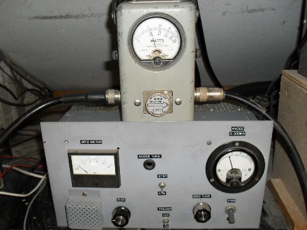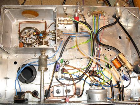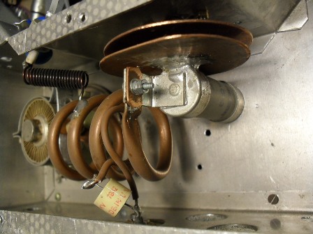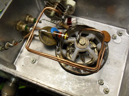

This linear uses a single 4CX250b forced air cooled tetrode and produces 200 -250 pep watts output for a drive level of approximately 2 – 3 Watts.The linear has proved to be extremely stable and easy to tune when in use. The circuit is very simple; the biggest challenge is the physical mechanics of it. The photographs show how it is put together. Looking at the circuit diagram you can see just how simple it is; no neutralisation is used as the control grid of the valve is heavily swamped by the 1K resistor in the bias supply. L1 couples the transceiver output to the control grid of the valve via L2. L2/VC1 form a series tuned grid circuit. A seperate grid compartment is formed from a die-cast box, dimensions for the grid inductors are given in the circuit diagram. The round aperature in the grid compartment is for a vaccumm hose supplying forced air cooling to be plugged in. The anode tank coil is made from 6mm - 8mm copper tube ( copper car brake pipe is very good ). VR1 sets the standing bias for the valve; 50mA- 70mA seems optimal for this linear when in SSB service. The anode current meter allows easy tune up and monitoring of the valve. VC2 and L3 form a series tuned tank cicuit, Vc2 is formed from some all -thread rod, two round copper disks (5.5cm diameter) one of which is soldered to a cartridge fuse ( Must be open circuit! ) to form the fixed plate and the other is soldered to the all - thread rod to form the moving plate. Be sure to have a good low inductance/resistance path to ground on the moving plate as there are high circulating RF currents present here. L4 is the output coupling link, and should be ajusted for optimum coupling/efficiency, be sure it is well insulated from L3 as this has the full HT present on it, insulation/spacing from L3 is paramount. The output change over relay used was salvaged from an old Europa set, these are fine for this power level providing the contacts are closed BEFORE any RF is applied to them and RF has CEASED before the contacts are opened (otherwise the arc produced will destroy the contacts and could also damage the valve), hence the timed delay circuit for RLY2 and the hold circuit for RLY3. Although it is a linear amplifier, I mainly use it in class C for FM work on 2m. Bias is set so the valve is heavily cut off, five Watts of drive power produce 200 Watts output for a anode current of approximately 150mA. The small perforated square cover on the amplifier front panel is the HT fuse; I used a panel mounting 20mm fuse holder mounted on a plexiglass plate and a hole in the front panel was cut to allow at least 1cm spacing between the fuse holder and the metal panel. Do NOT use ordinary glass fuses for the HT fuse, ceramic sand filled fuses (microwave oven type) are to be recomended. Lethal voltages are used in this circuit so extreme caution is advised.Here are a couple of larger photos power output measurement and the anode compartment , the top deck


Barry Zarucki M0DGQ
HOME